Installation
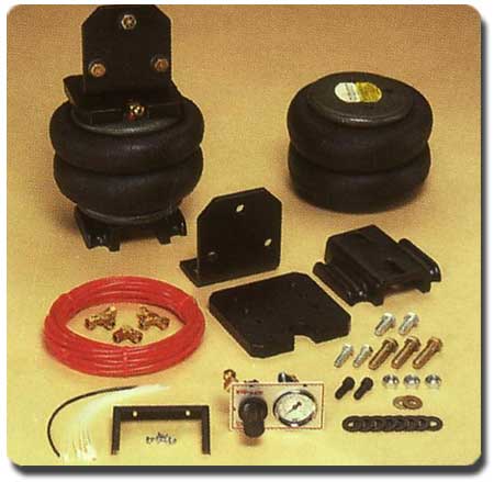
Air Helper Springs and Single Cab Control Kit
STEP 1: Prepare the Vehicle.
With the vehicle on a solid surface, jack up the vehicle's front axle, let the axle down on the jack stands and remove the wheels.
STEP 2: Removing the axle spring pad stop cushion.
Remove one axle spring pad stop cushion and replace with bottom casting item #4, re-torque "U" bolts. Remove spring pad stop cushion on opposite side and replace with bottom casting item #4, re-torque "U" bolts. Note: Bellows have built-in bumpers. Only replace "U" bolts if needed.
STEP 3: Installing top angle bracket.
It is important that the center of the top angle bracket, item #1, is aligned with the center of the bottom casting item #4. Using a square, draw a pencil line on the truck frame centered with the bottom casting. Take top angle bracket and align center mounting hole with pencil line on truck frame, clamp bracket to truck frame making sure that the bottom of the angel bracket is flush with the bottom of the truck frame. Using the bracket as a template, mark the hole locations on the frame. Remove the bracket from the frame and drill (3) 9/16" holes where marked. Note: In some cases the brake line bulkhead fitting has to be removed, and re-installed after top angle bracket is mounted. If top mounting hole is aligned with bulkhead fitting, re-drill this hole to 13/16" dia. Care should be taken to move fuel lines, electrical wire, etc. inside the truck frame from the path of the drill. Use the bolts, washers and nuts supplied in the hardware kit to mount the brackets.
STEP 4: Bellow installation.
Install 90 degree fitting in bellow, see fig. #2, pointing to the inside of the truck frame. Install mounting plate item #2 to the bellow with slot in the mounting plate over the 90-degree fitting. Install the bellow to the bottom mounting casting and the mounting plate to the top angle bracket. Note: Make sure that the bellows are clear of any truck parts and are installed straight. Tighten all bolts and nuts. WARNING: Do not inflate assembly, which it is unrestricted. Assembly must be restricted by suspension or other adequate structure. Do not inflate beyond 100 PSI. Improper use or over-inflation may cause assembly to burst, causing property damage and/or sever personal injury.
STEP 5: Installation of control panel and air lines.
Select a location inside the vehicle cab for mounting control panel item #1. Install a union tee item #3 in air supply line to windshield wiper motor, driver's air seat, or other constant air supply. Connect 1/4" dia. tubing item #2, from union tee to inlet side of pressure regulator of control panel. You may have to drill through the firewall. If so, make sure that the hole is free of sharp edges. Run 1/4" dia. tubing item #2 from outlet port on regulator, through the firewall if needed, to the air springs. Install union tee item #3 to connect air springs.
STEP 6: Check the air system.
Once the control panel and tubing is installed, inflate the air system and check the fittings for air leads with a solution of soap and water. If a lead is detected correct the fitting installation. This now completes the installation. The wheels and tires should be re-installed.
NOTE: With a load on your truck, and the air springs inflated, you must have at least one-inch clearance all around the air bellows. FOR BEST RIDE use only enough air pressure in the air springs to level the vehicle when viewed from the side. Inflate the air springs to maintain this height under any condition of load. Too much air pressure in the air springs will result in a stiffer ride. Too little air pressure will allow the vehicle to bottom out and not provide the improvement in handling that is possible. To prevent possible damage, maintain a minimum of 2 PSI in the Loadshare bellows at all times.
| ITEM | PART NO. | QTY. D.S. |
QTY. S.S. |
DESCRIPTION |
|---|---|---|---|---|
| 1 | 20167-B | 2 | 1 | Angle Bracket |
| 2 | 20166-B | 2 | 1 | Top Plate |
| 3 | HS 10086 | 2 | 1 | Dbl.Convolute Air Spring |
| 3 | HS 10110 | 2 | 1 | Sgl.Convolute Air Spring |
| 4 | 20168-C | 2 | 1 | Bottom Mounting |
| 5 | HS 10088 | 6 | 3 | Hex Head Cap Screw 1/2" unc x 2" long |
| 6 | HS 10087 | 4 | 2 | Hex Head Cap Screw 1/2" unc x 1" long |
| 7 | HS 10091 | 16 | 8 | Washer 1/2" dia. structural |
| 8 | HS 10090 | 6 | 3 | Locknut 1/2" unc |
| 9 | HS 10089 | 4 | 2 | Allen Head Screw 3/8" unc x 1" long |
| 10 | HS 10092 | 4 | 2 | Washer 3/8" dia. structural |
| 11 | HS 10095 | 4 | 2 | Hex Head Cap Screw 3/8" unc x 1" long |
| ITEM | DESCRIPTION | QTY | PART NO. |
|---|---|---|---|
| 1 | Control Panel Assembly | 1 | 20109 |
| Panel | 1 | 20110 | |
| Bracket | 1 | 20111 | |
| Regulator | 1 | HS 10037 | |
| Pressure Gauge | 1 | HS 10035 | |
| Female Connector 1/8" x 1/8" | 1 | HS 10008 | |
| 90° Male Elbow 1/8" x 1/8" | 1 | HS 10009 | |
| 90° Male Elbow 1/8" x 1/8" | 2 | HS 10031 | |
| Tubing 1/8" dia. | 12" | HS 10003 | |
| Self Tapping Screw | 7 | HS 10096 | |
| 2 | Tubing 1/4" dia. | 35' | HS 10097 |
| 3 | Union Tee | 2 | HS 10098 |
| 4 | 90" Male Elbow 1/4" x 1/4" | 2 | HS 10031 |
| 5 | Air Spring | 2 | HS 10086 |
| N/S | Nylon Tie 8" long | 6 | HS 10163 |